BASIC KNOLWEDGE: A
Amplifiers were one of the oldest electronic devices in use before the invention of transistors. Do you know that there are six main classes of power amplifiers available for your next design? The article discusses power amplifiers and their classes in detail.

Table of contents:
Power amplifiers are the hidden power behind electronics. They transform faint electrical signals into robust outputs, driving everything from concert hall speakers to medical imaging equipment. With various types available, each offering a unique balance between efficiency and distortion, power amplifiers ensure clear and impactful results.
1. What is a power amplifier?
The need for power amplifiers evolved throughout the 20th century from their usage in the music industry to high-power and RF applications. The early power amplifiers used to be large devices with cooling systems. In today’s times, power amplifiers are also found on SoCs (System on Chips).
Power amplifier definition
A power amplifier is a device that amplifies an input low-voltage low-current signal into a high-voltage high-current signal at the output. Power amplifiers are capable of delivering large voltage and currents to the load. In simple words, a power amplifier increases the strength of an input signal and delivers it to the output circuitry.
Power amplifier symbol
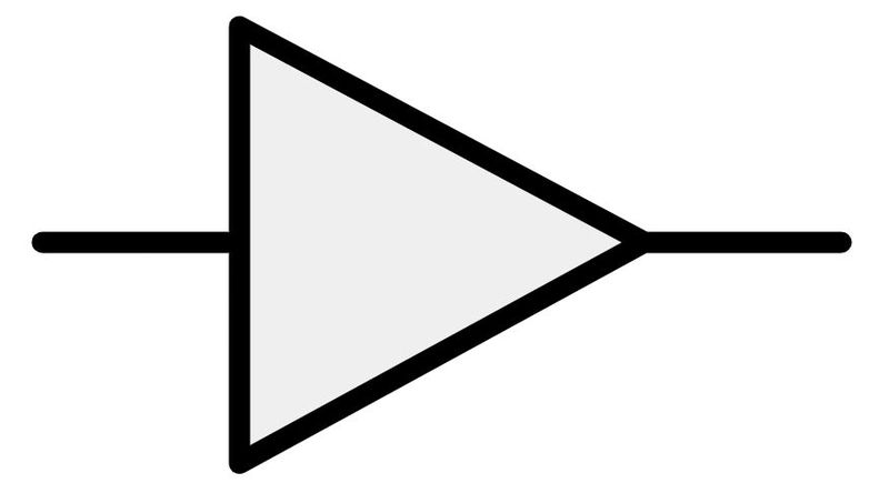
A power amplifier is represented in terms of BJT or FET in schematics and circuit diagrams. However, the most common representation of any amplifier is a “triangular shape”.
2. Power amplifier stages
An amplifier can have multiple stages. Each stage is responsible for performing a particular function. There are three stages in power amplifiers: the input stage, amplification stage, and output stage. However, the diagram below details five stages of power amplifiers for better understanding. Although coupling is present between each stage, this diagram represents a separate coupling stage towards the output.

Power amplifier stages are individual circuitry within the same power amplifier to perform different functions. All these stages collaboratively generate the output or deliver desirable power to the load. Multiple transistors and diodes are present in each stage to offer signal strength and gain. Amplifier stages remove harmonics and distortion from the amplified signal to maintain signal integrity. It is important to consider impedance matching and efficiency for designing the power amplifier stages.
Input stage
The input signal is processed before the amplification starts. The input to power amplifiers is usually an AC signal but it can be DC in certain applications like motor control systems.
Amplification stage
The amplification stage performs the main signal-strengthening function of the power amplifier. Also known as the voltage amplification stage, this stage is responsible for the voltage gain of the power amplifier.
Driver stage
The voltage amplification stage does not provide enough current to drive the output stage. The primary function of the driver stage is to provide sufficient current gain that controls the output stage of the power amplifier.
Coupling stage
The coupling stage ensures that the signal from one stage is sent to another while maintaining the quality. Transformers, common collector transistors (emitter-follower), and capacitors are used for coupling in power amplifiers.
Output stage
The output stage or final stage can consist of current limiters, filters, DAC (Digital-to-Analog Converters), and feedback. At last, the output stage is responsible for delivering the power to the load.
3. Why should we use a power amplifier?
A power amplifier is an important component of a power electronics system that goes on to convert an input low-power signal to a high-power signal at the output. In high-power applications, load demands high power to drive the output device. High power means high current. Low-power amplifiers are not reliable in such applications. As a result, various low-power amplifiers are connected to the input side of a power electronic system.
All low-power amplifiers are voltage amplifiers. All voltage amplifiers are small signal amplifiers. Simply put, a voltage amplifier is capable of only delivering a high-voltage but low-current signal at the output. Voltage amplifiers are unsuitable or “not enough” in power electronics because of a limited output current capability. Moreover, general-purpose op-amps also fall into the category of voltage amplifiers.
Power amplifiers are found at the output side of an electronics system, which is directly connected to the load. This is because power amplifiers are capable of delivering high power at the load. Power Amplifier is a type of current amplifier because it converts a low-power input signal into a high-power output signal. Sometimes a power amplifier is called a large signal amplifier.
Why are amplifiers needed to improve the strength of a signal?
If the signal strength is weak in any application, there won’t be proper communication, sound quality, sensitivity, and transfer of power. The presence of a power amplifier improves signal strength to ensure that there is no loss of information, connectivity, and the presence of any jammed (or lagged) signal. On a deeper level, amplification improves current flow and voltage levels in a circuit.
4. Power amplifier types
Power amplifiers can be categorized into various types considering their operation and application. It is important to note that power amplifier types and power amplifier classes are categories of power amplifiers. However, this article establishes power amplifier classes in a separate dedicated section.
Based on operation
By considering the power amplifier operation, power amplifiers can be categorized into three types: linear, switching, and digital power amplifiers.
Linear Amplifiers
A linear amplifier is a type of power amplifier in which its operation is dependent upon the conduction angle or portion of the input signal for which the transistor conducts. Class A amplifiers, class B amplifiers, class AB amplifiers, and class C amplifiers are a type of linear power amplifiers. These amplifiers either have low efficiency or distorted outputs because a high current flow causes a voltage drop across the resistor.
Switching Amplifiers
A switching amplifier rapidly turns on and turns off power transistors for high-frequency operation. Switching amplifiers do not rely on conduction time for amplifying the input signal. As a result, switching power amplifiers have high efficiency, low distortion, low power dissipation, and smaller size compared to their linear counterparts. Class D amplifiers and class E amplifiers are types of switching amplifiers.
Digital Amplifier
The above-mentioned linear and switching power amplifiers use analog techniques for amplification. A digital amplifier implements DSP (Digital Signal Processing) techniques to amplify the signal and generate a digital output. However, digital output can be converted to analog by a DAC at the output stage. Class D amplifiers and class E amplifiers are partially digital but still analog amplifiers. Class T amplifiers are “digital switching” amplifiers.
Based on application
Power amplifiers can be further categorized into audio and RF amplifiers based on applications.
Audio amplifier
The world’s first audio power amplifier was invented in 1912 by the American Inventor Lee de Forest. The very first audio power amplifier could transform low-power audio signals from radios and electric guitars to the kind of sound we hear from loudspeakers! For example, National Semiconductor Corp.’s LM380 is a popular power audio amplifier.
RF amplifier
An RF “radio frequency” amplifier operates for radio frequencies- 30kHz to 300 GHz. Generally, a power amplifier with a tuned LC circuit is used in RF applications. Class C amplifiers and class E amplifiers are types of RF amplifiers. However, “Proper” RF amplifiers are not typical power amplifiers as they are manufactured and designed very differently for high-frequency functionalities.
5. Power amplifier classes
Power amplifier classification or simply “power amplifier classes” are based on the duration for which the amplifier conducts.
Q-point establishes and adjusts operating conditions (biasing conditions) for power amplifiers. Simply put, power amplifier operation is dependent upon the position of the Q-point on the load line. Let us first explain Q-point through a graphical representation. Here, the transfer characteristics of an NPN BJT are shown.
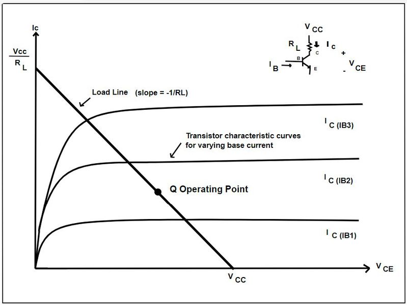
Q-point is a point chosen on the transfer characteristics of a transistor. Transfer characteristics of an NPN BJT in common emitter configuration is the relationship between output current IC on the Y-axis and output voltage VCE on the X-axis for a given base current IB.
Q-point is the point of operation of the transistor at which no input voltage signal is applied. At the Q-point, steady-state DC current and voltage are present for operation, as shown in the graph above. Q-point is also known as operating point, quiescent point, or biasing point.
Quiescent current is taken into consideration while explaining power amplifiers. In power BJTs, the quiescent current is the collector current. Similarly, the quiescent current is the drain current for FET power amplifiers. All the classes of power amplifiers are explained with the help of power BJTs.
The efficiency of power amplifiers is defined as the ratio of output and input power.

Where,
Input power incorporates losses: Pin= Pout + Plosses


Class A Amplifier
“Class A amplifier type amplifies 100 % of the input signal at the output.”
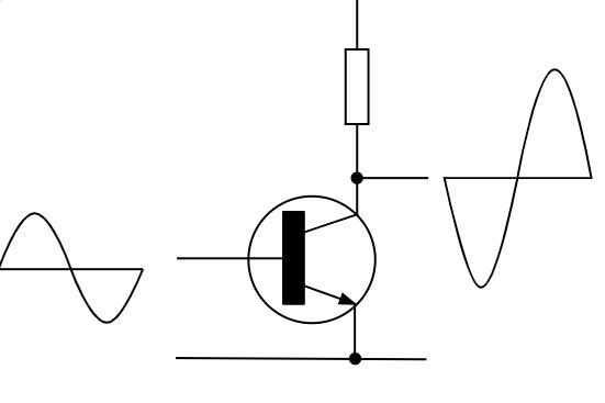
The transistor used in this class A amplifier is a single-power BJT in a common emitter configuration. The sinusoidal input is given to the base of the power transistor. The collector terminal is connected to the load resistor. As per the flow of the base current, the collector current starts to flow in the circuit. Both base and collector currents are in phase with each other. However, the collector current slightly lags behind the base current.
The power transistor is turned on to conduct the full cycle duration of the input AC signal. The output amplified signal is obtained for a full cycle or 360 degrees of the input signal. In simple words, class A amplifiers allow amplification for a complete input cycle. The Q-point is adjusted to be at the center of the load line. The power transistor always remains in the active region and never enters states of saturation, and cut-off.
As the power transistor remains in the active region, voltage, and current are high throughout the operation of class A amplifiers. The harmonic fluctuations are low in class A amplifiers. It means that the class A amplifier produces an undistorted output. Class A amplifiers have a property of inversion, i.e. generating an inverted output waveform.
The efficiency of class A power amplifiers is the lowest, about 25-30 %, among all power amplifier classes. A large amount of power is dissipated in the form of heat. Large heat sinks are needed to keep class A amplifiers cool. Sometimes a Darlington pair is used to improve the current handling capabilities of class A amplifiers.
Choosing class A amplifiers in your design results in the removal of distortion from the signal. Even though class A amplifiers are power amplifiers, they are still used in simple circuits and as small signal amplifiers. The disadvantages of using a class A amplifier are low efficiency and wastage of power in the form of heat.
Class B Amplifier
“Class B amplifier amplifies 50 % of the input signal at the output.”
The transistor used in this class B amplifier is a single-power BJT in a common emitter configuration. The sinusoidal input is given to the base of the power transistor. The power transistor is forward-biased to operate in the active region for half a cycle of the input signal. The base current initiates the collector current flow. For the negative half cycle of the input signal, the power transistor enters the cut-off region. The transistor is reversed-biased and remains off.
The conduction angle of class B amplifiers is 180 degrees. The output amplified signal is obtained for a half cycle or 180 degrees of the input signal. The Q-point is adjusted to be in the cut-off region. The power transistor always remains on for the active operation and remains off in the cut-off region. As a result, class B amplifiers produce output voltage waveforms for half cycles. In simple words, class B amplifiers allow amplification for a half-input cycle.
The resulting output waveform is not sinusoidal because only 50 % of the input signal is amplified. It results in a significant harmonic distortion in the output. There is another form of distortion, called crossover distortion, which occurs when power transistors transition from on to off states. It occurs because of discontinuity in the output signal compared to the point where the input signal “crosses” zero.
To improve performance, two class B amplifiers are used together to conduct respective half cycles. Such a configuration where each power transistor conducts for 180 degrees is called a push-pull class B amplifier. The reason that this is called a push-pull amplifier is because when one power transistor is “pushed” into conducting mode, the other is “pulled” out of the conducting mode.
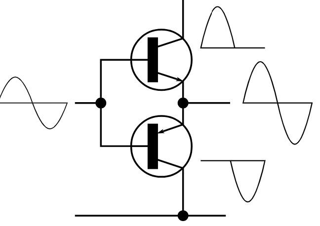
It is important to note that push-pull amplifiers are not always of class B. Push-pull amplifiers can be of any power amplifier class type. In simple words, push-pull is a configuration rather than a class. As the power transistor remains off for a half cycle, there is less heat dissipation. As a result, class B amplifiers have a high theoretical efficiency of about 78.5 %.
Class AB Amplifier
“Class AB amplifier amplifies more than 50 % but less than 100 % of the input signal at the output.”
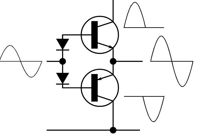
The conduction angle of the class AB amplifier is more than 180 degrees but less than 360 degrees. It means that the conduction period is always more than half a cycle but less than a full cycle. As a result, the output amplified signal is obtained for more than half a cycle but less than the full cycle of the input signal. In simple words, class AB amplifiers allow amplification for slightly more than half the input cycle. The Q-point is adjusted to be slightly above the cut-off region.
Usually, a class A B amplifier is used in push-pull configuration. Two power transistors used in this class A B amplifier are a BJT common emitter configuration. A power transistor always remains on for more than half a cycle and vice versa. The complete output waveform is shown for half cycle and significantly for the remaining half cycle. Such a waveform reduces crossover distortion in the circuit. This is because the time period for which the power transistor remains nearly off is lesser compared to class B amplifiers.
Another way is to use two complementary transistors. One NPN and another PNP. The complementary nature of the transistors automatically cancels the second harmonic component. Class AB amplifiers try to combine features of both class A and class B amplifiers. The efficiency of class A B amplifiers is less than class B amplifiers, i.e. less than 78.5 %.
Class C Amplifier
“Class C amplifier amplifies less than 50 % of the input signal at the output.”
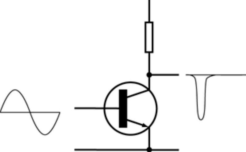
The conduction angle of the class C amplifier is less than 180 degrees. The Q-point is adjusted below the cut-off region. The output amplified signal is obtained for less than half a cycle of the input signal. In simple words, class C amplifiers allow amplification for a short time.
Generally, a single power transistor in common emitter configuration is used in class C amplifier type. The power transistor is biased below the cut-off region. It means that the collector current flows for less than half a cycle in the form of pulses.
As the transistor remains on for significantly less time compared to all other power amplifier classes, there is less power dissipation. As a result, class C amplifiers have a high efficiency of about 95 %. The class C amplifier efficiency is highest among power amplifier classes.
The drawback of class C amplifiers is the high amount of distortion in the output signal. The output of class C amplifiers is heavily distorted even more than class B amplifiers. Hence, class C amplifiers cannot be used as audio amplifiers. The best solution is to use an LC-tuned circuit as the load for improving performance.
An input AC signal in the form of current pulses is given to the tuned circuit. The train of current pulses fed to the tuned circuit at resonant frequency generates sinusoidal output voltage oscillations. However, the use of class C amplifiers with a tuned circuit is limited to a single resonant frequency in RF applications.
| Power Amplifier Class | Construction | Operating cycle or Conduction Angle | Linearity | Distortion | Signal Fidelity | Power Dissipation | Efficiency | Applications |
| Class A Amplifier | Simple | 360 degrees | Very High | No distortion | Highest | Highest | 50 % | Audio amplifiers, IF amplifiers, and high-voltage gain amplifiers |
| Class B Amplifier | Complex | 180 degrees | Moderate | Crossover distortion | Moderate | Low | 78.5 % | Audio systems: TVs, and public address systems |
| Class AB Amplifier | Complex | 180 < conduction angle > 360 | High | Low | High | Moderate | <78.5 % | CD players, TVs, and audio systems |
| Class C Amplifier | Simple | conduction angle < 180 | Lowest | Highest | Lowest | Lowest | 95 % | RF transmitters |
Class D Amplifier
“Class D amplifier is a type of switching amplifier that uses digital modulation techniques like PWM to drive the output stage.”
All the classes before the class D amplifier were dependent upon the conducting period of the power transistor. In class D amplifiers, the conduction angle of the amplifier varies with PWM (Pulse Width Modulation). In short, the conduction angle is not as important in class D amplifiers compared to the previous linear amplifiers. Class D amplifiers are also known as switching amplifiers or PWM amplifiers.
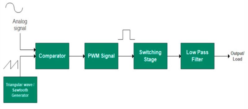
Class D amplifiers offer an efficiency of about 80-95 % and low power dissipation due to the use of MOSFETs. In addition, class D amplifiers are smaller in size than the other power amplifier classes. The associated heat sinks are also smaller in size. Class D amplifiers can be manufactured through CMOS logic and integrated on a chip. However, class D amplifiers have moderate signal quality.
An audio sinusoidal analog signal is the main information signal in class D amplifiers. There is a triangular wave generator or sawtooth waveform oscillator in the circuit. Output from the triangular wave generator and input analog signal are fed into a comparator. The comparator compares the two analog signals to generate a digital output in the form of a PWM signal.
Simply put, the audio analog signal modulates the carrier signal to generate a PWM output. The PWM signal controls the switching stage of the class D amplifier, which consists of MOSFETs. The sinusoidal signal is retrieved through two passive low-pass filters at the output stage. There can also be a feedback stage. However, class D amplifiers are not digital amplifiers but are analog amplifiers that use PWM. The presence of the letter “D” in class D amplifiers is a chronological nomenclature, not a depiction of the “D” of the digital amplifier.
Class E Amplifier
“Class E amplifier is an RF amplifier with high efficiency and signal quality”
Similar to power class D amplifiers, class E amplifiers are a type of switching amplifiers. However, class E amplifiers are used for RF applications. In simple words, class D amplifiers are audio power amplifiers and class E amplifiers are a type of tuned switching RF amplifiers.
Class E amplifiers turn on the MOSFETs in the amplification stage when there is no voltage across the device. As a result, E amplifiers eliminate switching losses to offer a high efficiency of about 90-95 %. There is a significant reduction in parasitic capacitance at RF frequencies that improves signal fidelity further.
Additional: Class T Amplifier
“Class T amplifier is a digital switching amplifier with high efficiency and signal fidelity.”
The original class T amplifier was a patented product of the American company Tripath Technology. Class T amplifiers are types of digital switching amplifiers that function through the company’s proprietary “digital power processing” technology. Later, more manufacturers came up with a similar class T amplifier.
The invention of the class T amplifier aimed to offer the same efficiency but better sound quality compared to power class D amplifiers. Class T amplifiers have an efficiency of about 80-90 %, the same as class D amplifiers. However, class T amplifiers do not rely on PWM for operation.
| Power Amplifier Class | Construction | Linearity | Signal Fidelity | Power Dissipation | Efficiency | Application |
| Class D Amplifier | Moderately complex | Moderate | Moderate to high | Low | 80-90 % | Audio amplifier |
| Class E Amplifier | Complex | High | High | Low | 90-95 % | RF amplifier |
| Class T Amplifier | Complex | High | High | Low | 80-90 % | Audio amplifier |
There are more power amplifier classes like F, G, H, I, J, S, etc. However, they are modified versions of the six main classes.
6. Power amplifier advantages
Power amplifiers offer a range of advantages that make them essential components in various electronic systems. These include:
- Power amplifiers ensure the delivery of high-current and high-voltages to the load.
- Power amplifiers have support for feedback control mechanisms.
- Power amplifiers require a robust power supply to function.
- Power amplifiers increase current sourcing capabilities in a power electronics system.
- Power amplifiers use simple circuitry like power BJTs and MOSFETs to operate.
- Most power amplifiers have simple to moderately complex designs.
- Some power amplifiers have a fast transient response.
- Output impedance matching is possible in all power amplifiers.
- Power amplifiers are cost-effective.
7. Power amplifier disadvantages
While power amplifiers provide significant benefits, they also come with some drawbacks to consider:
- Power amplifiers dissipate large amounts of heat.
- All power amplifiers are bulkier and are mounted on large heat sinks.
- Power amplifiers with a coupled transformer occupy an even larger surface area.
- Power amplifiers incur various types of distortions like harmonic, crossover, intermodular, second harmonic, phase, and frequency distortion.
- h-parameters cannot be completely used to perform analysis for power amplifiers.
- Power amplifier design is always a trade-off between efficiency and signal fidelity.
8. Power amplifier applications
Power amplifiers play a crucial role in many technologies, boosting signals for diverse functionalities.
Current-operated loads
Power amplifiers supply large currents to current-operated loads like speakers, motors, current transformers, etc.
Audio systems
Power amplifiers are used in loudspeakers, musical instruments, CD players, stereos, theaters, concerts, TVs, and mobile phones for high-quality sound.
RF transmitters
Power amplifiers are used in RF transmission in broadcasting stations, wireless communications, satellite communication, and radar systems.
Electronic instrumentation
Power amplifiers are used with electronic instruments like sensors, transducers, multimeters, and bridges in testing and conditioning applications.
Medical imaging
MRI and ultrasound systems have various electrical components. Power amplifiers are used in their imaging equipment to amplify these associated signals.

